To simulate polarization in RayLab turn on Polarization Raytracing in the model Options window.
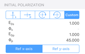
You can then specify the initial polarization of the rays in the properties window for the Object. The available options include:
- Horizontal or vertical linearly polarized light
- Left or Right Handed Circular polarized light
- Or arbitrary polarization state expressed using a Jones vector.
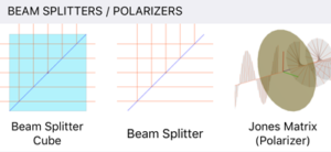
A variety of polarizing components can be modeled using the “Jones Matrix (Polarizer)” optical element.
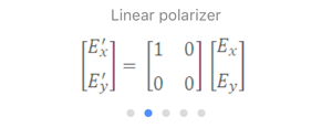
The Jones Matrix is a 2×2 complex matrix which describes the effect of the component on the polarization of the incident beam. This element assumes that the incident rays are normal to the surface.
For more details on Jones Calculus see: https://en.wikipedia.org/wiki/Jones_calculus
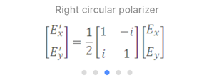
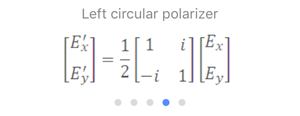
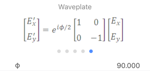
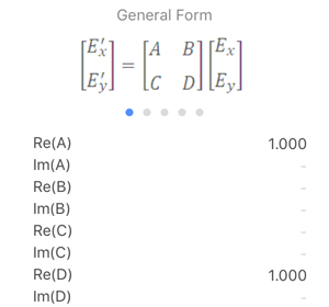
The Jones Matrix element allows you to select matrices for a Linear polarizer, Right circular polarizer, or Left circular polarizer. You also have the option to model waveplates (retarders) such as a quarter-wave or half-wave plates. Finally, you have the option to define an arbitrary Jones Matrix by specifying the real and imaginary components of the 2×2 matrix.
You can view the results of the polarization ray tracing in a number of ways:
- In the 3D layout view a representation of the electric field is displayed along each ray segment.
- You can use the Polarization Analyzer window which displays the polarization state of each ray as it intersects the image surface.
Below is a sample model which displays results of polarization ray tracing for a rotating quarter-wave plate and three fold mirrors.